**********************************************************************************************
Piston pumps are either radial or axial.
a. Radial. In a radial piston pump (Figure 3-14), the pistons are arranged like wheel spokes in a short cylindrical block. A drive shaft, which is inside a circular housing, rotates a cylinder block. The block turns on a stationary pintle that contains the inlet and outlet ports. As a cylinder block turns, centrifugal force slings the pistons, which follow a circular housing. A housing’s centerline is offset from a cylinder block’s centerline. The amount of eccentricity between the two determines a piston stroke and, therefore, a pump’s displacement. Controls can be applied to change a housing’s location and thereby vary a pump’s delivery from zero to maximum.

Figure 3-15 shows a nine piston, radial piston pump. When a pump has an uneven number of pistons, no more than one piston is completely blocked by a pintle at one time, which reduces flow pulsations. With an even number of pistons spaced around a cylinder block, two pistons could be blocked by a pintle at the same time. If this happens, three pistons would discharge at one time and four at another time, and pulsations would occur in the flow. A pintle, a cylinder block, the pistons, a rotor, and a drive shaft constitute the main working parts of a pump.

(1) Pintle. A pintle is a round bar that serves as a stationary shaft around which a cylinder block turns. A pintle shaft (Figure 3-16) has four holes bored from one end lengthwise through part of its length. Two holes serve as an intake and two as a discharge. Two slots are cut in a side of the shaft so that each slot connects two of the lengthwise holes. The slots are in-line with the pistons when a cylinder block is assembled on a pintle. One of these slots provides a path for a liquid to pass from the pistons to the discharge holes bored in a pintle. Another slot connects the two inlet holes to the pistons when they are drawing in liquid. The discharge holes are connected through appropriate fittings to a discharge line so that a liquid can be directed into a system. The other pair of holes is connected to an inlet line.

(2) Cylinder Block. A cylinder block (Figure 3-17) is a block of metal with a hole bored through its center to fit the pintle’s and cylinder’s holes that are bored equal distances apart around its outside edge. The cylinder’s holes connect with the hole that receives a pintle. Designs differ; some cylinders appear to be almost solid, while others have spokelike cylinders radiating out from the center. A cylinder’s and pintle’s holes are accurately machined so that liquid loss around a piston is minimal.

(3) Pistons. Pistons are manufactured in different designs (see Figure 3-18). Diagram A shows a piston with small wheels that roll around the inside curve of a rotor. Diagram B shows a piston in which a conical edge of the top bears directly against a reaction ring of the rotor. In this design, a piston goes back and forth in a cylinder while it rotates about its axis so that the top surface will wear uniformly. Diagram C shows a piston attached to curved plates. The curved plates bear against and slide around the inside surface of a rotor. The pistons’ sides are accurately machined to fit the cylinders so that there is a minimum loss of liquid between the walls of a piston and cylinder. No provision is made for using piston rings to help seal against piston leakage.

(4) Rotors. Rotor designs may differ from pump to pump. A rotor consists of a circular ring, machine finished on the
inside, against which the pistons bear. A rotor rotates within a slide block, which can be shifted from side to side to control the piston’s length of stroke. A slide block has two pairs of machined surfaces on the exterior so that it can slide in tracks in the pump case.
(5) Drive Shaft. A drive shaft is connected to a cylinder block and is driven by an outside force such as an electric motor.
b. Axial Piston Pumps. In axial piston pumps, the pistons stroke in the same direction on a cylinder block’s center line (axially). Axial piston pumps may be an in-line or angle design. In capacity, piston pumps range from low to very high. Pressures are as high as 5,000 psi, and drive speeds are medium to high. Efficiency is high, and pumps generally have excellent durability. Petroleum oil fluids are usually required. Pulsations in delivery are small and of medium frequency. The pumps are quiet in operation but may have a growl or whine, depending on condition. Except for in-line pumps, which are compact in size, piston pumps are heavy and bulky.
(1) In-Line Pump. In an in-line piston pump (Figure 3-19, diagram A), a drive shaft and cylinder block are on the same centerline. Reciprocation of the pistons is caused by a swash plate that the pistons run against as a cylinder block rotates. A drive shaft turns a cylinder block, which carries the pistons around a shaft. The piston shoes slide against a swash plate and are held against it by a shoe plate. A swash plate’s angle causes the cylinders to reciprocate in their bores. At the point where a piston begins to retract, an opening in the end of a bore slides over an inlet slot in a valve plate, and oil is drawn into a bore through somewhat less than half a revolution. There is a solid area in a valve plate as a piston becomes fully retracted. As a piston begins to extend, an opening in a cylinder barrel moves over an outlet slot, and oil is forced out a pressure port.

(a) Displacement. Pump displacement depends on the bore and stroke of a piston and the number of pistons. A swash plate’s angle (Figure 3-19, diagram B) determines the stroke, which can vary by changing the angle. In a fixed angle’s unit, a swash plate is stationary in the housing. In a variable unit’s, it is mounted on a yoke, which can turn on pintles. Different controls can be attached to the pintles to vary pump delivery from zero to the maximum. With certain controls, the direction of flow can be reversed by swinging a yoke past center. In the center position, a swash plate is perpendicular to the cylinder’s, and there is no piston reciprocation; no oil is pumped.
(b) Components. The major components of a typical, fixed-displacement in-line pump are the housing, a bearing-supported drive shaft, a rotating group, a shaft seal, and a valve plate. A valve plate contains an inlet and an outlet port and functions as the back cover. A rotating group consists of a cylinder block that is splined to a drive shaft, a splined spherical washer, a spring, nine pistons with shoes, a swash plate, and a shoe plate. When a group is assembled, a spring forces a cylinder block against a valve plate and a spherical washer against a shoe plate. This action holds the piston shoes against a swash plate, ensuring that the pistons will reciprocate as the cylinder turns. A swash plate is stationary in a fixed displacement design.
(c) Operation. A variable-displacement in-line pump operates the same as a fixed angle except that a swash plate is mounted on a pivoted yoke. A yoke can be swung to change a plate angle and thus change a pump’s displacement. A yoke can be positioned manually with a screw or lever or by a compensator control, which positions a yoke automatically to maintain constant output pressure under variable flow requirements. A compensator control consists of a valve that is balanced between a spring and system pressure and a spring loaded, yoke-actuating piston that is controlled by a valve. A pump’s compensator control thus reduces its output only to the volume required to maintain a preset pressure. Maximum delivery is allowed only when pressure is less than a compensator’s setting.
(2) Wobble-Plate In-Line Pump. This is a variation of an in-line piston pump. In this design, a cylinder barrel does not turn; a plate wobbles as it turns, and the wobbling pushes the pistons in and out of the pumping chambers in a stationary cylinder barrel. In a wobble plate pump, separate inlet and outlet check valves are required for each piston, since the pistons do not move past a port.
(3) Bent-Axis Axial Piston Pump. In an angle- or a bent-axis-type piston pump (Figure 3-20), the piston rods are attached by ball joints to a drive shaft’s flange. A universal link keys a cylinder block to a shaft so that they rotate together but at an offset angle. A cylinder barrel turns against a slotted valve plate to which the ports connect. Pumping action is the same as an in-line pump. The angle of offset determines a pump’s displacement, just as the swash plate’s angle determines an in-line pump’s displacement. In fixed-delivery pumps, the angle is constant. In variable models, a yoke mounted on pintles swings a cylinder block to vary displacement. Flow direction can be reversed with appropriate controls.
From Wikipedia, the free encyclopedia
A radial piston pump is a form of hydraulic pump. The working pistons extend in a radial direction symmetrically around the drive shaft, in contrast to the axial piston pump.
Construction[
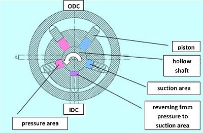
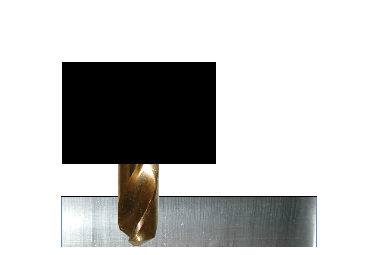
Picture 1: inside impinged radial piston pump
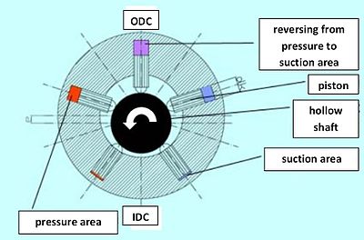
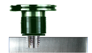
Picture 2: outside impinged radial piston pump
The stroke of each piston is caused by an eccentric drive shaft or an external eccentric tappet (e.g., stroke ring).
When filling the workspace of the pumping pistons from "inside" (e.g., over a hollow shaft) it is called an
inside impinged (but outside braced) radial piston pump
(picture 1). If the workspace is filled from "outside" it's called an
outside impinged radial piston pump (but inside braced)
(picture 2).
[citation needed]
Function[edit]
The general mode of operation will be explained at the movement of one pumping piston by means of picture 1:
The outer ring for bracing of the pumping pistons is in eccentric position to the hollow shaft in the center. This eccentricity determines the stroke of the pumping piston.
The piston starts in the inner dead center (IDC) with suction process. After a rotation angle of 180° it is finished and the workspace of the piston is filled with the moved medium. The piston is now in the outer dead center (ODC). From this point on the piston displaces the previously sucked medium in the pressure channel of the pump.
Attributes[edit]
These kinds of piston pumps are characterized by the following advantages:
- high efficiency
- high pressure (up to 1,000 bar or 14000psi)
- low flow and pressure ripple (due to the small dead volume in the workspace of the pumping piston)
- low noise level
- very high load at lowest speed due to the hydrostatically balanced parts possible
- no axial internal forces at the drive shaft bearing
- high reliability
A disadvantage is the bigger radial dimensions in comparison to the
axial piston pump, but it could be compensated with the shorter construction in axial direction.
Applications[edit]
Due to the hydrostatically balanced parts it is possible to use the pump with various
hydraulic fluids like mineral oil, biodegradable oil, HFA (oil in water), HFC (water-glycol), HFD (synthetic ester) or cutting emulsion. That implies the following main applications for a radial piston pump:
- machine tools (e.g., displace of cutting emulsion, supply for hydraulic equipment like cylinders)
- high pressure units (HPU) (e.g., for overload protection of presses)
- test rigs
- automotive sector (e.g., automatic transmission, hydraulic suspension control in upper-class cars)
- plastic- and powder injection molding
- wind energy


