Open as word document
UNIT I STATICS OF PARTICLES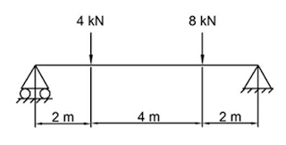
6. Determine the
support reactions of the beam as shown in the figure.
339 October
2018
Time— Three hours
(Maximum Marks: 75)
(N.B: (1) Q.No. 8 in PART - A
and Q.No. 16 in PART — B are compulsory. Answer any FOUR
questions from the remaining in each PART - A and PART - B
(2) Answer division (a) or division (b) of each question in PART -
C.
(3) Each question carries 2 marks in PART — A, 3 marks in
Part - B and 10 marks in PART — C. I
PART - A
1. What are the characteristics of force?
2. State Hooke’s law.
3. What is meant by temperature stress?
4. List out the stresses, induced in thin cylindrical shells.
5. What is beam?
6. Define polar modulus.
7. List the various types of springs.
8. Define moment of inertia.
PART - B
9. Distinguish between force of friction and limiting force of friction.
10. Define co-efficient of friction.
ii. Differentiate between repeated loading and cyclic loading.
12. What is centroidal axis and axis of reference?
13. What is cantilever beam and simply supported beam?
14. Write down the assumptions made in theory of pure torsion.
is. Compare closely coiled and open coiled helical spring.
16. What is UDL and UVL?
PART — C
17. (a) (I) What are the essential conditions for equilibrium of rigid body?
(ii) State the law of static friction.
(Or)
(b) The magnitude of the resultant of two concurrent forces with an
included angle of 90° between them is ‘ROOT OF 3 kN. When the included angle between the
forces is 60°, the magnitude of their resultant is ROOT OF 19 kN.
Find the magnitude of the two forces.
18. (a) List and explain the various mechanical properties of materials.
(Or)
(b) A mild steel specimen 25mm rod diameter was subjected to an axial pull
of 100 kN. An extension of 0.25 mm was noted on a gauge length of 300 mm and a
decrease in diameter of 0.00595 mm was observed. Find the values of Poisson’s
ratio and Young’s modulus of the material.
19. (a) Find the centroid of an I section having top flange 150mm X 25mm,
web 160mm X 25mm and bottom flange 200mm X 25mm.
(Or)
(b) Determine the change in diameter and change in volume of spherical
shell 2m in diameter and 12 mm thick subjected to an internal pressure of 2
N/mm2. Assume E=2x10⁵ N/mm2 and Poisson’s
ratio = 0.25.
20. (a) Draw the SFD and BMD for a simply supported beam subjected to a point
load ‘W’ at its mid point.
(Or)
(b) A wooden beam of rectangular section 100mm X 200mm is simply supported
over a span of 6 m. Determine the UDL it may carry, if the bending stress is
not to exceed 7.5 N/mm2. Estimate the concentrated load it may carry
at the centre of the beam with the same permissible stress.
21. (a) With neat sketches, explain the various types of springs.
(Or)
(b) A solid shaft 20 mm diameter transmits 10 kW at 1200 rpm. Calculate the
maximum intensity of shear stress induced and the angle of twist in degrees in
a length of l m. If modulus of rigidity
for the material of the shaft is 8x10⁴ N/mm2.
(Maximum Marks: 75)
(N.B: (1) Q.No. 8 in PART - A and Q.No. 16 in PART - B are compuLsory. Answer any FOUR questions from the remaining in each PART - A and PART - B
(2) Answer division (a) or division (b) of each question in PART - C.
(3) Each question carries 2 marks in PART - A, 3 marks in Part — B and lOmarks in PART-C. I
PART - A
1. Define resultant of forces.
2. What is meant by coplanar force?
3. Define Poisson’s ratio.
4. Define polar moment of nerta.
5. Define neutral axis.
6. Define section modulus.
7. Define stiffness of a spring.
8. Distinguish between centre of gravity and centroid.
PART - B
9. Differentiate between static friction and dynamic friction.
10. Define hardness and list its characteristics.
11. Differentiate between thin cylinder and thick cylinder.
12. What is point load and uniformly distributed load?
13. Write down the assumptions made in theory of simple bending.
14. What is laminated spring? List its applications.
15. List out the advantages of hollow shaft over solid shaft.
16. Define support. List the various types of loads.
[Turn over
185/570—1
1 Define force. State its unit
2. Define fatigue.
3. Define stress with its unit.
4. Write perpendicular axis theorem
S Define thin and thick cytindricat shell.
6. State the classifications of beams
7. Define stiffness of shaft.
8. State Varignon’s theorem
PART-B
9. Explain parallel law of forces
10. Define free body diagram and wnte the necessary conditions for the equilibrium of rigid bodies.
11. Define strain energy and proof resilience
12. Describe composite bar.
13. Define centre of gravity and centroid.
14 State and explain parallel axis theorem.
15. Explain the types of Loading.
16. How do you find the power transmitted by the shaft?
PART - c
17. (a) The resultant of two forces acting at an angle of 600 is ‘root of 148 N. If the same forces are acting at right angles their resultant is 10N. Determine the magnitude of the two forces.
(Or)
(b) The magnitude of the resultant of two concurrent forces including angle of 90° between them is root of 13 kN. When the included angle between the forces is 60°, the magnitude of their resultant is root of 19 kN. Find the magnitude of the two forces.
18. (a) (i) Explain the behaviour of mild steel in tension up to rupture with stress and strain diagram.
(ii) Calculate the strain that can be stored in ci. steel bar 70mm in diameter and 6 m long, when subjected to a pull of 200 kN. Assume E=2x10⁵ N/mm2.
(Or)
(b) A bar of length 150 mm is 60 mm in diameter. It is subjected to an axial pull of 400 kN. The extension in length and contraction in diameter were found to be 0.25mm and 0.02mm respectively. Determine the values of elastic constants.
19. (ci) (I) Find the centroid of ‘I’ section having the top flange 100 mm x 20 mm, web 150 mm X 10 mm and bottom flange 200 mm x 20 mm.
(ii) Explain the radius of gyration.
(Or)
(b) A thin cylinder diameter 860mm diameter and 3 m long has a shell thickness of 10mm. If the shell is subjected to an internal pressure of 2.5N/mm2, determine (i) change in diameter (ii) change in length and (iii)change in volume.
20. (a) A cantilever beam 6m long carries three point loads 2 kN, 3 kN and 3 kN at a distance 1.5 m, 4 m and 6 m respectively from the fixed end. It also carries of udl of 1.5kN/m run spread over 4m from free end. Calculate SF and BM at salient points of the beam and sketch the SFD and BMD.
(Or)
-3-
(b) A simply Supported beam 5m long carries concentrated loads of 70 kN, 90 kN, 50 kN and 80 kN at a distance 1 m, 3 m 4 m and 4.5 m respectively from left hand support. Find the support reaction. Draw SFD and BMD.
21. (a) Compare the weight of solid shaft with that of hollow shaft for the same material and length and designed to reach the same maximum shear stress when subjected to same torque. Assume inside diameter of hollow shaft is equal to 3/5 of external diameter.
(Or)
(b) A solid shaft 120 mm diameter transmits 180 kW at 240 rpm. Calculate the maximum intensity of shear stress induced and the angle of twist in degrees for a Length of 16 m. Take C = 0.8x10⁵N/mm2.
123 April
2018
Time - Three hours (Maximum Marks: 75)
(N.B: (1) Q.No. 8 in PART - A and Q.No. 16 in PART - B are compuLsory. Answer any FOUR questions from the remaining in each PART - A and PART - B
(2) Answer division (a) or division (b) of each question in PART - C.
(3) Each question carries 2 marks in PART - A, 3 marks in Part — B and lOmarks in PART-C. I
PART - A
1. Define resultant of forces.
2. What is meant by coplanar force?
3. Define Poisson’s ratio.
4. Define polar moment of nerta.
5. Define neutral axis.
6. Define section modulus.
7. Define stiffness of a spring.
8. Distinguish between centre of gravity and centroid.
PART - B
9. Differentiate between static friction and dynamic friction.
10. Define hardness and list its characteristics.
11. Differentiate between thin cylinder and thick cylinder.
12. What is point load and uniformly distributed load?
13. Write down the assumptions made in theory of simple bending.
14. What is laminated spring? List its applications.
15. List out the advantages of hollow shaft over solid shaft.
16. Define support. List the various types of loads.
[Turn over
185/570—1
-2-
PART - C
17. (a) (i) Explain the various methods of supports and reactions.
(ii) State the laws of dynamic friction.
(Or)
(b) The resultant of two concurrent forces is 1500N and angle between the forces is 90. The resultant makes an angle of 36o with on the force. Find the magnitude of each force.
18. (a) State and explain the three types of elastic constants.
(Or)
(b) List out the various alloying elements used in steel and explain their major effects.
19. (a) Find the values of lxx and Iyy of a T-section 120mm wide, 120mm deep overall. Both the wed and flange are 10mm thick.
(Or)
(b) A long steel tube 70mm internal diameter and wall thickness 2.5mm has closed ends and subjected to an internal pressure of 10 N/mm2. Calculate the magnitude of hoop stress and longitudinal stresses setup in the tube. If the efficiency of the longitudinal joint is 80%, state the stress which is affected and what is its revised value?
20. (a) Write down the expressions for section modulus of rectangular and circular beam.
(Or)
(b) A simply supported beam of span l0 m carries an udi of 20 kN/m over the left half of the span and a point load of 30kN at the mid span. Draw SFD and BMD. Find also, the position and magnitude of maximum bending moment.
21. (a) Prove the torsion equation.
(Or)
(b) The mean diameter of a closely coiled helical spring is 5 times the diameter of wire, If elongates 8mm under an axial pull of 120N. If the permissible shear stress is 40N/mm2, find the size of wire and number of coils in the spring. N =0.8 X10⁵ N/mm2.
185/570—2
April 2017 -
Cancelled Exam
PART A 1 Define force. State its unit
2. Define fatigue.
3. Define stress with its unit.
4. Write perpendicular axis theorem
S Define thin and thick cytindricat shell.
6. State the classifications of beams
7. Define stiffness of shaft.
8. State Varignon’s theorem
PART-B
9. Explain parallel law of forces
10. Define free body diagram and wnte the necessary conditions for the equilibrium of rigid bodies.
11. Define strain energy and proof resilience
12. Describe composite bar.
13. Define centre of gravity and centroid.
14 State and explain parallel axis theorem.
15. Explain the types of Loading.
16. How do you find the power transmitted by the shaft?
PART - c
17. (a) The resultant of two forces acting at an angle of 600 is ‘root of 148 N. If the same forces are acting at right angles their resultant is 10N. Determine the magnitude of the two forces.
(Or)
(b) The magnitude of the resultant of two concurrent forces including angle of 90° between them is root of 13 kN. When the included angle between the forces is 60°, the magnitude of their resultant is root of 19 kN. Find the magnitude of the two forces.
18. (a) (i) Explain the behaviour of mild steel in tension up to rupture with stress and strain diagram.
(ii) Calculate the strain that can be stored in ci. steel bar 70mm in diameter and 6 m long, when subjected to a pull of 200 kN. Assume E=2x10⁵ N/mm2.
(Or)
(b) A bar of length 150 mm is 60 mm in diameter. It is subjected to an axial pull of 400 kN. The extension in length and contraction in diameter were found to be 0.25mm and 0.02mm respectively. Determine the values of elastic constants.
19. (ci) (I) Find the centroid of ‘I’ section having the top flange 100 mm x 20 mm, web 150 mm X 10 mm and bottom flange 200 mm x 20 mm.
(ii) Explain the radius of gyration.
(Or)
(b) A thin cylinder diameter 860mm diameter and 3 m long has a shell thickness of 10mm. If the shell is subjected to an internal pressure of 2.5N/mm2, determine (i) change in diameter (ii) change in length and (iii)change in volume.
20. (a) A cantilever beam 6m long carries three point loads 2 kN, 3 kN and 3 kN at a distance 1.5 m, 4 m and 6 m respectively from the fixed end. It also carries of udl of 1.5kN/m run spread over 4m from free end. Calculate SF and BM at salient points of the beam and sketch the SFD and BMD.
(Or)
(b) A simply Supported beam 5m long carries concentrated loads of 70 kN, 90 kN, 50 kN and 80 kN at a distance 1 m, 3 m 4 m and 4.5 m respectively from left hand support. Find the support reaction. Draw SFD and BMD.
21. (a) Compare the weight of solid shaft with that of hollow shaft for the same material and length and designed to reach the same maximum shear stress when subjected to same torque. Assume inside diameter of hollow shaft is equal to 3/5 of external diameter.
(Or)
(b) A solid shaft 120 mm diameter transmits 180 kW at 240 rpm. Calculate the maximum intensity of shear stress induced and the angle of twist in degrees for a Length of 16 m. Take C = 0.8x10⁵N/mm2.
UNIT I STATICS OF PARTICLES
2&3
marks
1. State
the principle of transmissibility
2. State
the parallelogram law of forces
3. State
the triangular law
4. State
the polygon law.
5. State
varignon’s theorem.
6. Define
free body diagram.
7. What
are the necessary and sufficient conditions for the equilibrium of rigid bodies
in two dimension?
8. What
are the different types of support?
9. State
the Laws of static and dynamic friction
10. Define
limiting friction.
11. Define
co-efficient of friction
BIG
QUESTIONS
1. The following forces act at a
point
200N inclined at 30o
towards North of East
250N towards North
300N towards North West
250 N inclined at 40°
towards South of West
Find the magnitude and direction of
resultant force.
2. Five forces are acting on a particle. The
magnitude of the forces are 300 N, 600 N, l00N, 900N and ‘P. and their
respective angles with the horizontal are 0°, 60°, 135°, 210° and 270°.
If the vertical component of alt the forces is —1000 N, find the value of ‘P.
Also calculate the magnitude and the direction of the resultant force assuming
that 300N force acts towards the particle while all others act away from the
particle. (Oct 2017)(Oct 2016)
3. A
particle ‘O’ is acted upon by the following forces:
(i) 20 N inclined 30° to north of east.
(ii) 25 N towards the north.
(iii) 30 N towards north-west.
(iv) 35 N inclined 40° to south of west.
Find the magnitude and direction of the resultant force. APRIL_2017
4. Discuss the various types of supports with neat sketches and show the reaction components of each. APRIL_2017
5. The magnitude of the resultant of
two concurrent forces including on angle of 90° between them is square root of 13 kN. When the included angle between the forces is 60°, the
magnitude of their resultant is square root of 19 kN. Find the magnitudes of the two forces. (Oct 2017)

(Oct 2016)
UNIT
II DEFORMATION OF METALS
2&3
marks
1. Definition
of mechanical properties (Malleability. Ductility, Elasticity, Plasticity,
Fatigue, fatigue strength, creep, temperature creep)
2. Define
stress and strain
3. State
Hooke's law.
4. What
is meant by factor of safety?
5. Define
Lateral strain.
6. Define
Poisson's ratio.
7. Define
volumetric strain
8. Define
bulk modulus.
9. What is composite bar?
10. Define
strain energy
11. Define
proof resilience.
12. Define
modulus of resilience.
BIG
QUESTIONS
SIMPLE
STRESS AND STRAIN:
1. 1..A
steel rod 25 mm in diameter and 2 m long extends by 0.2 mm under a pull of 10
kN. Calculate the stress and strain in the rod. (APR12)
2. 2. A
steel rod of 20 mm diameter and 3 m long is subjected to an axial pull of 20
kN. Find the stress, strain and elongation in the bar, if the modulus of
elasticity of the material is 2 x 10⁵ N/mm2. (APR13)
3. 3. Find
the young's modulus of a brass rod of diameter 25mm and of length 250mm which
is subjected to a tensile load of 50kN when the extension of the rod is equal
to 0.3mm.
4. A
circular bar of 20mm diameter carries a tensile load of 30kN. Find the tensile
stress in the bar and the elongation in a length of 300mm. Take E = 2x10⁵
N/mm2.
5.
A Cement Concrete Cube of 150mm
Size Crushes at a load of 337.5 kN. Determine the working stress, if the factor
of safety is 3. (APR16)
6. A
mild steel bar of 1 meter length and 20mm diameter is subjected to a tensile
load of 20 kN. If the Young's modulus of the material is 2x10⁵ N/mm2,
determine the elongation produced.
7. (i)
A mild steel rod of 25mm diameter and 400mm long is subjected to an axial pull
of 75kN. If E=2x10⁵ N/mm2, determine the elongation of
the rod.(APR14)
CHANGE
IN DIMENSIONS AND STRAIN
1. A
steel rod 2 m long and 200 mm diameter is subjected to an axial pull of 45 kN.
Find the changes in length, diameter and volume of the rod. Take E = 0.2 x 10⁵
N/mm2 and m = 0.3. (APR12)
2. A
steel rod 5m long and 30mm in diameter is subjected to an axial pull of 50kN.
Determine the change in length, diameter and volume of the rod. Take E = 2x10⁵
N/mm2 and Poisson's ratio 0.25. (OCT13)
3. A
steel bar of 25mm diameter and a length of 1m is subjected to a pull of 25 kN.
If E=2x10⁵ N/mm2, find the elongation, decrease in
diameter and increase in the Volume of the bar. Take m= 0.4. (APR17)
4. A
steel bar of 400mm long, 60mm wide and 15mm thick is subjected to an axial
tension of 100kN. Calculate the final dimensions. Take E=2x10⁵ N/mm2
and 1/m=0.3(APR14)
5.
A mild steel flat 20mm wide, 15mm
thick and 2m long carries an axial pull of 30 kN. Find the final volume of the
flat if E=2x10⁵ N/mm2 and Poisson's ratio 1/m = 0.25. (OCT14)
6. A
steel bar 400mm long, 60mm wide, and 15mm thick is subjected to an axial
tension of 100kN. Calculate the final dimensions and change in volume of the
bar. Take E=2x10⁵N/mm2 and 1/m= 0.3. (OCT15)
RELATION BETWEEN E, N & K
7. The
Young's modulus and rigidity modulus of a given material are 120 GPa and 50 GPa
respectively. Find the values ofPoisson’s ratio and Bulk modulus. (OCT12)
8. A bar of steel 30 mm diameter and 500 mm long
is subjected to an axial load of 75 kN. It is found that the diameter has
contracted by 1/240 mm. If the modulus of rigidity is 0.8x10⁵ N/mm2,
calculate the values of (1) Poisson’s ratio (2) young's modulus and (3) Bulk
modulus. (APR13)
9. A
circular bar of length 150mm and diameter of 50mm is subjected to an axial pull
of 400kN. The extension in length and Contraction in diameter were found to be
0.25mm and 0.02mm respectively after loading. Calculate (i) Poisson's ratio
(ii) Young's modulus (iii) Modulus of rigidity and (iv) Bulk
modulus.(OCT16)
COMPOSITE
BAR
1. A
copper rod of 20mm in diameter is enclosed in a steel tube of 30mm inner
diameter and 40mm external diameter. The ends are rigidly fixed and it is
subjected to an axial pull of 30kN. Find the stresses induced in the rod and
tube and elongation of this composite bar in a length of 1 m. Take Young's
modulus of steel as 2x10⁵ N/mm2 and young's modulus of
copper as 1x10⁵N/mm2. (OCT12)
2. A
copper rod 30 mm diameter is surrounded tightly by a cast iron tube of 60 mm
outside diameter and the ends are fastened firmly together. When the composite
bar is subjected to 12kN, find the stress and the load shared by each. Also
find the change in length of the composite bar in a length of 100 mm. Take E
for cast iron is 1.2 x 10⁵ N/mm2 and E for copper as 1 x
105 N/mm2. (OCT13)
3. A
composite tube consists of a steel tube of 140mm internal diameter and 160 mm
external diameter and an outer brass tube 160mm internal diameter and 180mm
external diameter. Length of each tube is 140mm. The composite tube carries an
axial load of 900kN. Find the stress and the load carried by each tube. Take E
for steel as 2x10⁵ N/mm2 and E for brass as 1x10⁵N/mm2.
(APR14)
4.
A solid copper rod 36mm in diameter
is rigidly fixed inside a steel tube of 45mm inside diameter and 50mm outside
diameter. This composite section is subjected to cn axial pull of 100kN.
Determine (i)the stresses induced in the rod and tube and (ii) the total
extension of the composite section in a length of 1 meter. E for copper =
1.1x10 N/mm, E for steel = 2x10 N/mm. (APR15)
5. Two
vertical wires each 3mm diameter and 3m long jointly support a load of 2kN. One
wire is made of steel and the other wire is made of aluminium. If the wires
stretch elastically 3mm, find the load taken by each wire and the value of
Young's modulus of aluminium. Given E for steel is 2x10⁵ N/mm2.
(OCT15)
6. Two
vertical wires, each 2.5mm dia and 5m long jointly support a weight of 2.5 kN.
One wire is of steel and the other is of different material. If the wires
stretch 6mm elastically, find the load taken by each and the value of Young's
modulus for the second wire. The Young's modulus of steel wire is 2x10⁵
N/mm2. (APR17)
UNIT
III GEOMETRICAL PROPERTIES OF SECTIONS AND THIN SHELLS
2&3
marks
1. Define
Moment of Inertia
2. State
parallel axes theorem.
3. State
perpendicular axes theorem
4. Define
center of gravity
5. Define
centroid
6. Define
centroidal axis.
7. Define
Axis of symmetry.
8. Define
Polar moment of Inertia?
9. Define
radius of gyration.
10. Differentiate
Thin and thick cylindrical shell.
11. Define
hoop stress(circumferential stress) and longitudinal stress
UNIT
III Problems
T- SECTION
1.
Find the centroid of a T-section with
flange l00 mm x 30 mm and web l20 mm x 30 mm. APR 14
2.
Find the centroid of oninverted T section with flange
150 x 20 mm and web 100 x 25 mm. OCT
12
3.
Find
IXX, IYY and KXX and KYY of a T section with flange
150mm x 20mm and web 100mm x 20mm. APR
17
4.
Find the values of IXX and IYY
of a T Section 120 mm wide and 120 mm deep overall. Both the web and flange are
10 mm thick. APR 13
ANGLE
or L - SECTION
5.
Find the
centroid of unequal angle section 100 x 80 x 20 mm.
6.
An angle section is of 100 mm wide and
120 mm deep overall. Both the flanges of the angle are 10 mm thick. Determine
the moment of inertia about the centroidal axes X-X and Y-Y. OCT 16, OCT 15
7.
Find the position of centroid and calculate the values of IXXand IYY
for an angle section 30 mm x 30
mm x 10 mm thick. APR 12
I
- SECTION
Equal Flanges
8.
Find the centroid of an I-section having
top flange and bottom flanges of size 200 mm x 40 mm and web 160 mm x 40 mm. OCT
13
9.
Find the
moment of inertia about the centroid co-ordinates axes of an I-section having
equal flanges 120 mm x 20 mm size and web 120 mm x 20 mm thick.
Unequal Flanges
10.
Find the centroid of an I-section having
top flange l50mm x40 mm, web l60 mm x 40 mm and bottom flange 200 mm x 40 mm. OCT
14
11.
An I-section has the top flange 120 mm x
20 mm thick, web 180 mm x 20 mm thick and the bottom flange 200 mm x 40 mm
thick. Calculate the moment of inertia IXX and IYY and
also calculate the radius of gyration KXX and KYY.APR 16, APR 15, APR
14
CHANNEL
OR C - SECTION
Equal Flanges
12.
Find the
centroid of channel section 100 x 50 x 15 mm.
13.
A channel section is of size 300 mm x 100 mm overall.
The base as well as the flanges of the channel is 12 mm thick. Determine the
values of IXX and IYY. Also find its radius of gyration
about its centroidalaxes. OCT
12
UNIT
IV SF AND BM DIAGRAMS OF BEAMS AND THEORY OF BENDING
1. Give
the classification of beams.
2. Define
shear force and bending moment
3. What
are the types of loads?
4. State
the theory of simple bending,
5. State
the Assumptions made in theory of simple bending***
6. Define
Neutral axis.
7. Define
section modulus.
8. Write
down bending equation.
Cantilever
Beam
1.
A cantilever
beam of 12m long carry loads of 6 kN, 4 kN, 7 kN and 3 kN at distances 4m, 7m,
10m and 12m respectively from the fixed end. Draw the SF and BM diagrams for
the cantilever beams. Find the maximum values of SF and BM. (APR 15)
2. A
cantilever beam of 4m long carries an udl of 20 KN/m over half of its length
from the free end. Draw the SF and BM diagrams. (APR17, OCT 12)
3. A
cantilever 6m long carries a concentrated load of 2kN, 2kN and 3kN at distances
of 2m, 4m and 6m respectively from the fixed end. In addition to, there is a
uniformly distributed load (udl ) of 1.5 N/m spread over the entire length of
the beam. Draw the SF and BM diagrams. (OCT 15)
4.
A cantilever of
span 5 m is loaded
with three point loads of 2kN each at 2 m, 4 m and 5 m from the fixed end in
addition to a UDL of 1 kN/m to a length of 4 m from the fixed end. Draw the S.F
and B.M diagrams. (APR 13)
Simply
Supported Beam
5.
A beam is simply supported at its ends
10 m apart. The beam carries loads of 4 kN, 3 kN and 5 kN at distances of 2m,
4.5m and 7.5m respectively from the left end. Draw the S.F. and B.M. diagrams.
(APR 16)
6. A
simply supported beam of span 6 m carries three point loads of 30 kN, 25 kN and
40 kN at 1 m, 3 m and 4.5 m respectively from the left support. Draw the SFD
and BMD and indicate the maximum value of bending moment. (OCT16)
7. A simply supported beam 6m long
carries an UDL of 2 kN/m runs over a
length of 3m from the right end.
Construct SFD and
BMD. Also find the position and magnitude of maximum bending moment. (OCT 12
8.
A simply supported beam of length 6m
carries an udl of 20 kN/m throughout its length and a point load of 30 kN at 2
m from the right support. Draw the SFD and BMD. Also find the position and
magnitude of maximum bending moment. (APR17, APR 14)
9. A
simply
supported beam of 5m span carries an udl of 2 kN/m over the entire span. In
addition the beam carries a point load of 4 kN at a distance of 2m from the
left support. Draw the SF diagram and bending moment diagram. (OCT 14)
10. A simply supported beam of span 10 m carries a u.d.I. of
20 kN/m over the left half of the span and a point load of 30 kN at the mid span. Draw S.F.D.
and BMD. Find also the position and magnitude of maximum bending moment. ( APR 12)
11.
A beam 8 m long is simply supported at its
ends. It carries an UDL of 1 kN/m over a length of left half of its span
together with concentrated loads of 2 kN, 3 kN and 2 kN at 2 m, 4 m and 6 m
respectively from the left hand support. Draw the S.F. and B.M. diagrams for
this beam and find out the magnitude and position of maximum bending
moment. (APR 13)
UNIT
V THEORY OF TORSION AND SPRINGS
1. State
the assumptions made in theory of torsion.
2. Compare
solid and hollow shafts.
3. Define
Polar modulus.
4. Define
torsional rigidity.
5. List
the Advantages of hollow shafts over solid shafts.
6. What
are the types of springs?
7. What
are the applications of laminated and coiled spring?
8. Difference
between open and closely coiled helical springs
9. What
are the types of coiled springs?
10. Define stiffness of spring
1.
Calculate the power transmitted by a shaft of 100mm diameter running at 250 rpm, if the shear stress in the shaft material is not to exceed 75N/mm2. (APR 17)(APR 15)(OCT12)
Calculate the power transmitted by a shaft of 100mm diameter running at 250 rpm, if the shear stress in the shaft material is not to exceed 75N/mm2. (APR 17)(APR 15)(OCT12)
2.
A solid circular shaft is to transmit a power of
360kW running at 300rpm. If the shear strength of the shaft material is 56N/mm2,
what should be the minimum diameter of the shaft.(APR 15)
3.
A solid shaft is transmitting 100kW power at 180
rpm. If the allowable stress is 60N/mm2, find the necessary diameter
for the shaft. The shaft is not to twist more than 1o in a length of
3m. Take C=80 kN/mm2.(APR
17)(OCT12)
4.
A solid shaft is subjected to a torque of 15 kNm.
Find the necessary diameter of the
shaft, if the allowable shear stress is 60 N/mm2 .The allowable
twist for every 20 diameters length of the shaft Take N=80N/mm2. (APR 12)
5.
A solid steel shaft 100mm diameter transmits 100kW
at 180rpm. Calculate the maximum intensity of shear stress induced and the
angle of twist in degrees for a length of 10m. Take C=0.8xl05 N/mm2.(APR 16)(OCT13)
6.
Calculate the power transmitted by a hollow shaft
of 110 mm external diameter and 80 mm internal diameter at 240 rpm. If the
maximum permissible shear stress is 80 N/mm2. (OCT13)
7.
A hollow shaft having inner diameter 0.6 times the
outer diameter is to replace a solid shaft of same material to transmit 550 kW
at 220rpm. Calculate the diameters of the hollow and solid shafts. Also
calculate the percentage savings in material. The allowable shear stress is
80N/mm2.(OCT16)(APR 13
similar)
8.
A solid shaft is to transmit 300kW at 180rpm. If
the shear stress of the material must not exceed 80N/mm2. Find the
diameter of solid shaft. What percentage saving in weight would be obtained if
this shaft were replaced by a hollow shaft whose internal diameter equals to
0.6 times the external diameter, and keeping the same length, material and
maximum shear Stress.(APR 14)
9.
A hollow
shaft of 300 mm outer diameter and 250mm inner diameter runs at 120rpm. The
maximum torque exceeds the mean torque by 30% and the maximum permitted shear
stress is 60N/mm2. Calculate the power transmitted and the angle of
twist in a length of 3m. Take C=9x10⁴ N/mm2.(OCT15)(OCT14)
i need m scheme important question
ReplyDelete