Thanks www.tndte.gov.in
****************
Open pdf drawings as pdf
***************


***********************************************************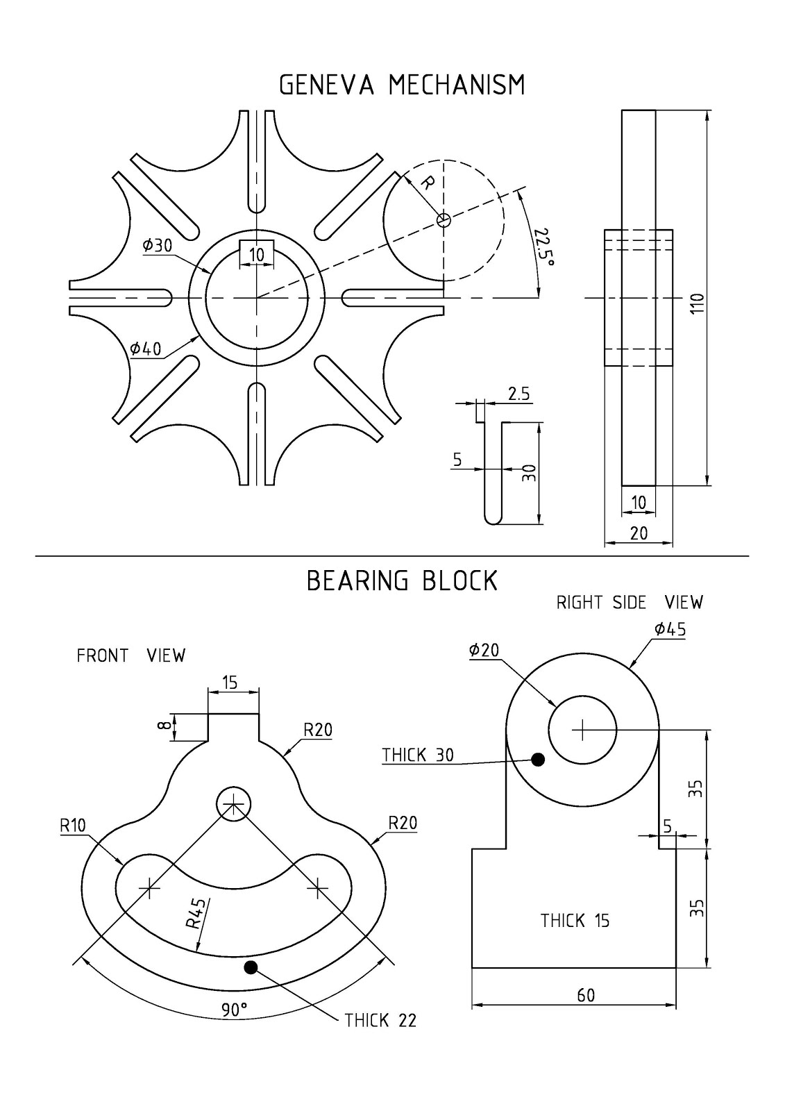


Geneva wheel
****************
Open pdf drawings as pdf
***************
***********************************************************
Open Drawings redrawn by R.Ramakutty as pdf***********************************************************
AutoCAD
3D - Introduction
WCS and UCS
There are
two coordinate systems: a fixed system called the world coordinate system (WCS)
and a movable system called the user coordinate system (UCS). By default, these
two systems are coincident in a new drawing.
By default when we start a new (blank)
drawing we use the World Coordinate System (WCS). This is (0,0,0) point. The
square in the crosshairs of UCS indicates the World Coordinate System. Normally in
2D views, the WCS X axis is horizontal and the Y axis is vertical. The WCS
origin is where the X and Y axes intersect (0,0). All objects in a drawing file
are defined by their WCS coordinates. However, it is usually more convenient to
create and edit objects based on the movable UCS.
Moving or rotating the UCS can make it easier to work on
particular areas of a drawing.
We can relocate the user coordinate system by UCS command
- Move the UCS by defining a new origin point.
- Align the UCS with an existing object.
- Rotate the UCS by specifying a new origin point and a point on
the new X axis.
- Rotate the current UCS a specified angle around the Z axis.
- Revert to the previous UCS.
- Restore the UCS to be coincident with the WCS.
- View makes the ucsicon
parallel to drawing screen.
Regions are two-dimensional areas we
create from closed shapes or loops. Closed polylines, lines, and curves are
valid selections. Curves include circular arcs, circles, elliptical arcs,
ellipses, and splines.
Regions are two-dimensional enclosed areas that have
physical properties such as centroids
Creating 3D Solids
Presspull
Click inside bounded areas to press or pull
and drag the mouse in the required Z direction and enter the height
We can create a new solid or surface by
sweeping an open or closed planar curve (profile) along an open or closed 2D or
3D path.of bounded areas
Select the objects or
edge subobjects to extrude.
Specify the height and
taper angle or select the path
Closed polylines, circles
and regions are only extruded to 3d solids
SWEEP
Creates a 3D
solid or surface by sweeping a 2D object(region) along a path.
LOFT
Creates a 3D solid or surface in the space between
several cross sections. To create a solid by lofting, first create a
set of cross sections. Then click the Loft button on the Modeling Toolbar.
REVOLVE
Select a closed region or closed
polyline to revolve.
To set the axis of revolution,
specify one of the following: The start and endpoint. Click to points on the
screen to set the axis orientation. ...
Press
Enter. To create a 3D solid the angle must be 360 degrees.
SLICE
Specify two points to define the
cutting plane.
Specify which side of the sliced object
to retain, or enter b (Both) to retain both sides.
UNION
Combines
selected 3D solids, surfaces, or 2D regions by addition.
SUBTRACT
Select the objects that you want to keep,
press Enter, then select the objects that you want to subtract. Objects
in the second selection set are subtracted from objects in the
first selection set.
INTERSECT
VISUALSTYLES
Creates and modifies visual styles and applies a visual
style to a viewport.
Create a
rectangular or cubical solid box.
Create a
solid wedge with rectangular or cubical faces.
Create a
pointed or frustum of a cone with a circular or elliptical base.
Create a
solid cylinder with a circular or elliptical base.
Create a
solid sphere using one of several methods.
Create a
solid pyramid with up to 32 sides.
Create a
ring-shaped solid that resembles the inner tube of a tire.
Solview
This command automates the manual process of
creating views, layers, and layout viewports for 3D models.
Note SOLVIEW must
be run on a layout tab. If the Model tab is current, the last active layout tab
is made current.
SOLVIEW places the viewport objects on the VPORTS layer,
which it creates if it does not already exist. The view-specific information
that is saved with each viewport you create is used by SOLDRAW to generate
the final drawing view.
SOLVIEW creates layers that SOLDRAW uses to place the
visible lines and hidden lines for each view, view
name-VIS, view name-HID,
view name-HAT, and a layer where
you can place dimensions that are visible in individual viewports, view name-DIM.
Soldraw
After using SOLVIEW, visible and hidden lines
representing the silhouette and edges of solids in the viewport are created and
then projected to a plane perpendicular to the viewing direction.
Select viewports to draw ...
Select objects: Select the
viewports to be drawn
3DROTATE : In a 3D view, displays the 3D
Rotate gizmo to aid in revolving 3D objects around a base point.
3DARRAY : For 3D rectangular
arrays, in addition to columns and rows, you also specify the number of levels
in the Z direction.
Enter the number of items in the
array
Specify the angle to fill (+=ccw,
-=cw) <360>
The specified angle determines how far the objects are
arrayed about the axis of rotation. A positive number produces a
counterclockwise array rotation. A negative number produces a clockwise array
rotation.
Rotate arrayed objects? [Yes/No]
<Y>: Enter y or n, or press Enter
3D Mirror.
Select the object to mirror.
Specify three points to define a mirroring plane.
Press Enter to retain the original objects, or enter y to delete
them.
Align.
Select the objects that
you want to align.
Specify a source point and
then the corresponding destination point. To rotate the object, specify a
second source point followed by a second destination point.
Press
Enter to end the command
Aim
:
To draw the geneva wheel 3d drawing
in AutoCad
Procedure
:
|
1. Hub:
|
Draw 2 concentric circles of radius 15 mm and 20
- Circle with center
point, radius option.
|
Draw the keyway (10 mm X 3 mm) -
Line, Offset, Trim
|
2. Wheel
|
Draw the top half of slot at 25 mm from the center of the hub(2.5 mm 30 mm x 2.5 mm ). - Line, Offset, Trim
|
Fillet the inner end with radius 2.5.
|
Mirror the bottom half.
|
Make a polar array of 8 slots.
|
Draw the circular arc between two
successive slots. (Line at 22.5
degree, line of 55 mm =radius of geneva wheel & vertical line from last
line, Circle, Trim)
|
Make a polar array of 8
arcs.
|
3. 3D Solid
Modeling
View
toolbar à SE Isometric view
|
Modeling
Toolbar à Presspull
Presspull
the the hub by clicking inside between
two circles to half thickness ( 10 mm ) in Z direction
|
Presspull
the the wheel by clicking inside between
hub and outline to half
thickness ( 5 mm ) in Z direction
|
View toolbar
à Front view
Mirror the bottom
half
|
Modeling
Toolbar à Union
Union the
two halves.
View
toolbar à SE Isometric view
|
Visual
Styles Toolbar à Conceptual , 2D
wireframe, 3D Hidden etc
|
4. Isometric view & Orthographic views
SOLVIEW must be run on a layout tab. If the Model
tab is current, the last active layout tab is made current
To create
isometric view , Set
UCS à View and give Solview à Ucsà
Current Ucs
Change view to main view (Front or Top view) in Model Tab
|
RESULT
:
The geneva wheel 3d drawing is drawn in AutoCAD
Bearing block
Aim :
To
draw the bearing block 3d drawing in AutoCAD
Procedure :
Bottom
portion of block
1.View
toolbar à
Front View
2.
Draw two lines from a point A à at -45 degree and at -135
degree.
3.
Draw three concentric circles of radius
45, 55, and 25 mm , with intersection point A as centre.
4.
Trim the circles outside the two lines
5.
Draw circles with 2P – 2 Point
option to connect circles of radii 25, 45 mm.
6.
Draw three circles of 20 mm radius with the centres of last drawn circles(R10)
and “A” point as centres. Draw a circle
of 5 mm radius with “A” point as centre
7.
Fillet the 20 mm radius circles on the left side and right side – with Radius = 15 mm.
8.
Draw the rectangle of 15 mm x 8 mm, at the top symmetrically.( Line, Offset and
Trim commands)
9.
Trim the unnecessary edges.
10.
View toolbar à
SE isometric View . Presspull -
click between outer and inner edges and pull
to Z-Thickness of 22 mm.
Middle and
top portion of block.
11.
View toolbar à
Right side View
12.
Draw a series of lines :: 60 mm to the right , 35 mm to the top, 5 mm to the
left, 35 mm to the top, 45 mm to the left, 35 mm downwards, 10 mm to the left
and 35 mm downwards.
13.
With midpoint of 45 mm line as centre, draw concentric circles of 22.5 mm and
10 mm radii.
14.
Erase 45 mm line.
15.
View toolbar à
SE isometric View. Presspull -
click inside the middle portion and pull
to Z-Thickness of 15 mm. Presspull -
click between outer and inner
circles and pull to Z-Thickness of 35 mm
16.
Move the the top portion 5 mm the right.
17.
Union the Middle and top portions.
Assembly
18.
Assemble and union the portions – Move and Union
19.
Isometric view & Orthographic views
creation :SOLVIEW must be run on a layout tab. If the Model tab
is current, the last active layout tab is made current.To create isometric
view , Set UCS à View and give Solview à Ucsà Current Ucs.Change view to main view (Front or Top view) in Model Tab
RESULT
:
The bearing block 3d drawing is drawn in AutoCAD
Bushed bearing
Aim
To draw the bushed bearing 3d
drawing in AutoCAD
Procedure
:
Half Block
(or) Half Body
1.View
toolbar à
Front View
2.
Draw a rectangle of 112 x 15 (Command : Rectang
, Explode(X) or Line)
3.
Draw two concentric circles of radius 25 and 16 mm at a height of 35 from the
base of rectangle.
4.
Draw vertical lines from the horizontal quadrant
points of the 25 mm radius circle downwards.
5.
Fillet with Radius 5 mm on both sides
6.
View toolbar à
SE isometric View . Presspull -
click between outer circle and bottom rectangle and pull to Z-Thickness of 20 mm.(half
thickness)------bottom of body
7. Presspull
- click between circles and pull
to Z-Thickness of 25 mm.(half thickness)
---------
top of body.
Bush (Draw full bush)
8.
View toolbar à
Front View
9.
Draw two concentric circles of radius 12.5
and 16 mm
10.
View toolbar à
SE isometric View . Presspull -
click between circles and pull
to Z-Thickness of 50 mm.(half thickness).
Full Block
11.
View toolbar à
Right Side View or Top View
12.
Mirror the other half of block .
13.
Union the the halves of block .
Slot & fillet at Rectangular
Base
14.
View toolbar à
Front View . Draw the slots at top of
rectangular base at both ends
15.
View toolbar à
SE isometric View . Presspull -
click in the slot area and press downwards
to make slot.
16.
Fillet the rectangular base at both ends.
Oil hole
17.
Make oil holes for block (Cone, Cylinder and union or two circles and loft) and bush (Cylinder) with extra length at the
bottom side at the top UCS in the SE Isometric view.
18.
Move the oil holes to block and bush repectively and Subtract.
Assembly
19.
Move bush to block.
RESULT
:
The bushed bearing 3d drawing is drawn in AutoCAD
 8. View toolbar à Top View
4. Gib and Cotter Joint
Aim :
To
draw the Gib and Cotter Joint 3d drawing in AutoCAD
Procedure :
1.
View toolbar à
Front View
2.
Draw the fork rod, square rod, gib and cotter.(Commands: Line, Rectang, Fillet,
Offset, Trim, Mirror)
3.
View toolbar à
SE isometric View .
4. Presspull - click inside the fork area and pull to
Z-Thickness of 38 mm
5.
Presspull - click inside the square rod area and pull to
Z-Thickness of 38 mm.
6.
Presspull - click inside the gib area and pull to
Z-Thickness of 12 mm.
7.
Presspull - click inside the cotter area and pull to
Z-Thickness of 12 mm.
9.
View toolbar à
SE isometric View (Or) UCS II toolbar à
Top UCS (Or) World UCS
10.
Draw a rectangle for slot in the
fork rod and square rod. Copy the rectangle to top face of the fork rod and
square rod. Presspull - click inside the rectangle and press downwards outside
the solid ---- in the fork rod. (Separately for the square rod)
Assembly
11.
Move the square rod to the fork rod.
Move gib and cotter
RESULT
:
The Gib and Cotter Joint 3d drawing is
drawn in AutoCAD
5. Screw Jack
Aim :
To draw the Screw Jack 3d drawing in AutoCAD
Procedure :
1. View
toolbar à
Front View
2. Create body of the Screw Jack :
Construct the half of the cross section and an
axis line for revolution.
Use Region
(Reg) command to create the closed 2d area.
Use Revolve
(Rev) command to create the 3d solid.
Select
the region and press enter
Specify
the start point of axis
Specify
the end point of axis
Specify
angle of revolution <360> : press enter
3. Similarly create all other parts
v Nut
v Screw Spindle
v Cup
v Special washer
v Set Screw
v Tommy Bar
4. Create a
hole in the screw spindle (A) at top
Copy the shank of the
set screw (b)at the top of the screw spindle
Subtract: select A first, press
enter and select B next and press enter. (A-B)
5. Create a
hole in the screw spindle at side.
Make a cylinder. Move
the cylinder to the screw spindle
Subtract this cylinder
from the screw spindle
6. Similarly
draw the half circular slots in the cup and slot in the set screw.
7. Assembly :
Move
the nut to the body.(align bottom of center of the collar of the nut à top center of body).
Move
the screw spindle to the nut.(align top center of the nut à bottom center of screw spindle head) and again move
the screw spindle upwards by 10 mm.
Move the cup to the screw spindle
(align bottom center of the cup à top center of screw
spindle head)
Move the washer and set screw.
RESULT :
The Screw Jack 3d drawing is drawn in AutoCAD.
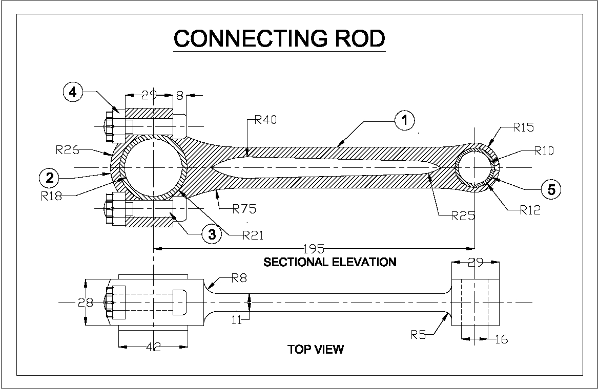
6. Connecting Rod
Aim :
To draw the Connecting Rod 3d drawing in
AutoCAD
Procedure :
1. View
toolbar à
Front View
2. Draw the big end and bush
Draw the small end and bush
Draw the I section connecting big end and small end
3. View toolbar à SE
Isometric View
4. Presspull
all the parts to half thickness.
Presspull big end
Presspull big end bush
Presspull small end
Presspull small end bush
Presspull the I-section flange
Presspull the I-section web or rib
5. View
toolbar à
Right Side View or Top view
Mirror all the parts
Union
6. View
toolbar à
SE Isometric View
UCS II toolbar à Right UCS
Make holes in top and bottom of the
big end
7 Split the
big end by Slice (SL) command.
8. Make
bolts and join the ends.
RESULT :
The Connecting Rod 3d drawing is drawn in AutoCAD.