Mariners Repository
 Collection of notes and literature on various topics ,simplified and presented as a one stop search .
Collection of notes and literature on various topics ,simplified and presented as a one stop search .
- Rajeev V Krishna
- I always believed in the fact that knowledge expands by sharing and proactive learning, and is a lifetime process. Concept based learning is the best way to understand and grow further . Knowledge is vast and scattered all over the net and in physical form of books .It takes effort, time and dedication to bring all in one place. This is a sincere effort to bring all my notes and collection over a period of two decades, simplified and open to all students and professionals . It will always be my sincere endeavor to update the pages from time to time as per technical advances , with support from colleagues, students , academia , professionals and fraternity in the industry.
Hydraulics Part 1 - Direction Control Valves
Direction control valves in Hydraulic systems are classified as follows:
1.Type of internal element for actuation : Poppet (piston or ball) , Rotary spool , sliding spool
2.Methods of Actuation : Manual , mechanical , Pneumatic , Hydraulic , electrical , Electronic or a
combination
3.Size : Nominal size , volume handled
4.Type of connection :Flanged , Pipe thread
Hydraulic notation

Check Valves :
These are the simplest type of hydraulic valves - allowing free flow in one direction and blocking the other side.There is a light spring holding the poppet valve in position , only to be lifted up when flow occurs overcoming the spring pressure in that direction.These are further classified based on direction as
- In line check valve (flow direction is in the same axis)


-Right angle check valve - flow direction is in right angles to the original flow.
Restricted flow check valve - has an orifice in the valve plate .These valves are used to control the rate of pressure rise or fall in a system.

Pilot operated check valves - need a pilot pressure to actuate the check valve


A typical application of pilot operated check valves - is accumulator unit powered by pump- as shown below.

Symbols


Methods of actuation:
Mechanical Actuation

Pneumatic/ Hydraulic

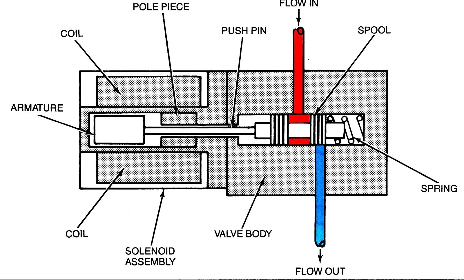
Electrical / Electronic actuation : By solenoids AC/DC , controlled by electronic logic.
The number of ports to and from determines a Two way , Three way or four way valve
Valves with machined spool (2 Way , 3 Way , 4 way valves )
Two way valves permit the flow from one pressure port to outlet port by change of spool

Three way valve have special spool configurations , permitting flow from pressure to two other ports at the same time.

Four way valves are present in five variations

1. Spring centered :
Two position spring centered has one actuator with spring to return
Three position spring centered has two actuators- with spring to return.

2.Two position spring offset : Spring holds the spool at one position and actuator changes condition opposite to spring condition

3.Two position Actuate to center : Valve is normally under one extreme condition held by spring - only to return to center position when actuated

4.Two position Detented : Valve spool is held in position by detent mechanism in one extreme position , to be changed upon actuation.

5.Spool center spool valves :
Open center - interconnects all ports - to remove pressure from end user to flow back into the tank
Closed center:- Closes all ports - pressure retained.
Tandem center: Blocks flow from end user ports - but connects pressure port to tank at low pressure- used in series circuits.
Float Center: - Pressure maintained at pressure port- but removed from other ports - used commonly with pilot operated check valve circuits.

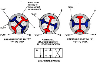
6.Rotary valve

Two stage valves
These are used to control fluids at high pressures , where the main valve is actuated by a pilot mechanism . The main purpose is to reduce pressure surges in the system and smooth operation.
They can be incorporated with stroke limiting of main spool or a throttle valve flow between pilot to main spool for smother transition , as shown below:

A pilot operated choke valve controlling spool is as below:

A symbolic representation of various two stage valves is as below:


2 comments: